Simple beam antenna - the G4ZU "Jungle Job"
Posted: Wed Mar 01, 2023 12:01 pm
Hi, while waiting for a medical check, I spent some time surfing the 'net and stumbled upon this page about Gordon "Dick" Bird (G4ZU)
https://www.essexham.co.uk/gordon-dick- ... nformation
and, at the bottom of the page, I saw an antenna design which immediately grabbed my attention, the one called "Jungle Job"

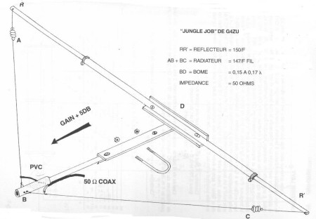
the antenna is as simple as effective, it's just a wire dipole with the arms placed at an angle and a reflector, the two form what we could call a "compact Yagi", and the angle between the dipole arms brings the dipole characteristic impedance to about 50 Ohm so allowing a good match to coax
The design hooked me, so I decided to go on and try modeling it in NEC once back home, the result is this 4NEC2 model which anyone can load and test (just click "select all" then copy the code snd paste it to notepad or the like, save the file as "jumglejob.nec" and load it in 4nec2)
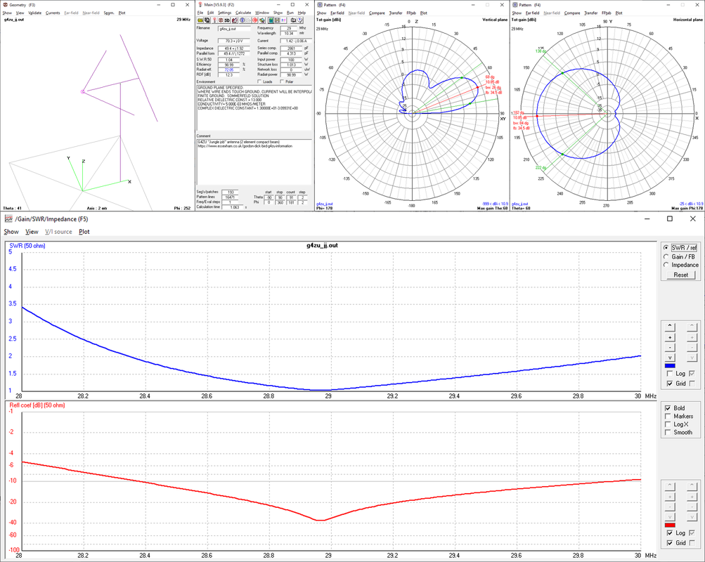
as you can see, I changed the calculation factors given by G4ZU for the dipole, reflector and boom lengths, I did that to optimize the antenna as much as possible, and the results are pretty good, the model, configured for the 10m band and with the antenna at an height of 0.6 lambda shows a gain of 10.9dBi with a good takeoff angle (the lowest is around 10° from horizon and offers gain of about 8 dBi), a front-back ratio of 34.5dB and an SWR covering almost the whole 10m band, not bad,
here are the results of the simulation

Later on, a friend of mine decided to give the antenna a spin, he built it "quick and dirty" by using some PVC pipes to form the structure and some insulated wire for the reflector and the dipole, the resulting antenna, while not nice to see, confirmed the results of the NEC simulation, showing good gain and F/B ratio and allowing some good contacts (daily skips to Australia from.Europe)
While probably not suitable for "POTA/SOTA", such a simple antenna may be a good resource for "from the car" activations or even for chasing SOTA/POTA activators, the overall size should be manageable for the 20 to 6 meters bands (not sure how it may work at V/UHF)
Nothing special, just hope it may be useful to some of the QRPers here, also since those 10dBi of gain will give quite a boost to the few W from the rig (and to the received signals, by the way)
https://www.essexham.co.uk/gordon-dick- ... nformation
and, at the bottom of the page, I saw an antenna design which immediately grabbed my attention, the one called "Jungle Job"

the antenna is as simple as effective, it's just a wire dipole with the arms placed at an angle and a reflector, the two form what we could call a "compact Yagi", and the angle between the dipole arms brings the dipole characteristic impedance to about 50 Ohm so allowing a good match to coax
The design hooked me, so I decided to go on and try modeling it in NEC once back home, the result is this 4NEC2 model which anyone can load and test (just click "select all" then copy the code snd paste it to notepad or the like, save the file as "jumglejob.nec" and load it in 4nec2)
Code: Select all
CM G4ZU "Jungle job" antenna (2 element compact beam)
CM https://www.essexham.co.uk/gordon-dick-bird-g4zu-information
CE

' frequency
SY freq=29.000              ' design frequency
SY wave=(300/freq)          ' wave length

' materials
SY copp=58000000            ' copper
SY alum=37700000            ' aluminium
SY stel=1390000             ' steel

' radius
SY wrda=0.0125              ' alum.pipe 25mm diam.
SY wrdb=0.0100              ' alum.pipe 20mm diam.
SY wrdc=0.0080              ' alum.pipe 16mm diam.
SY wire=0.00125             ' copper wire 2.5mm diam.
SY pole=0.025               ' support pole

' calc factors
SY dfac=144                 ' dipole factor (147)
SY rfac=145                 ' reflector factor (150)
SY bfac=0.236               ' boom factor (0.15...0.17)
SY hfac=0.60                ' height factor

' height, arms, boom
SY hght=(wave*hfac)         ' height from ground
SY darm=(dfac/freq)/2       ' single dipole arm
SY rarm=(rfac/freq)/2       ' single reflector arm
SY boom=(wave*bfac)         ' boom

' reflector
SY rsec=(rarm/3)            ' reflector sections
SY rena=rsec                ' end of first section
SY renb=rena+rsec           ' end of second section
SY renc=renb+rsec           ' end of third section

' dipole vertex angle
SY angl=97                  ' angle between arms
SY anga=90-(angl/2)         ' vertex angle of arm 1
SY angb=180-anga            ' vertex angle of arm 2

' segmentation
SY segm=51                  ' segments
SY segs=5                   ' segments

' feed
SY fwir=1                   ' feed element
SY fseg=1                   ' feed segment

' start of geometry

' dipole (copper wire)
GW  1 segm     0    0 hght (darm*sin(anga)) (darm*cos(anga))  hght wire
GW  2 segm     0    0 hght (darm*sin(angb)) (darm*cos(angb))  hght wire

' reflector sections (aluminium)
GW  3 segs boom     0 hght            boom             rena   hght wrda
GW  4 segs boom     0 hght            boom            -rena   hght wrda
GW  5 segs boom  rena hght            boom             renb   hght wrdb
GW  6 segs boom -rena hght            boom            -renb   hght wrdb
GW  7 segs boom  renb hght            boom             renc   hght wrdc
GW  8 segs boom -renb hght            boom            -renc   hght wrdc

' boom (aluminium)
GW 10 segs  0.2      0 hght           boom-0.8            0   hght wrda
GW 11 segs  boom-0.8 0 hght           boom                0   hght wrda

' mast (steel)
GW 12 segm  boom-0.8 0 hght           boom-0.8            0      0 pole

' end of geometry
GE 1

' ground parameters
GN  2  0  0  0  13  0.005

' elements loading

' dipole
LD  5  1  0  0  copp
LD  5  2  0  0  copp

' reflector
LD  5  3  0  0  alum
LD  5  4  0  0  alum
LD  5  5  0  0  alum
LD  5  6  0  0  alum
LD  5  7  0  0  alum
LD  5  8  0  0  alum

' boom
LD  5 10  0  0  alum
LD  5 11  0  0  alum

' mast
LD  5 12  0  0  stel

' enable ext kernel
EK

' feeding
EX 0 fwir fseg  0  1.0 0.0

' test frequency
FR 0 1 0 0 freq 1

' end of model
EN
here are the results of the simulation

Later on, a friend of mine decided to give the antenna a spin, he built it "quick and dirty" by using some PVC pipes to form the structure and some insulated wire for the reflector and the dipole, the resulting antenna, while not nice to see, confirmed the results of the NEC simulation, showing good gain and F/B ratio and allowing some good contacts (daily skips to Australia from.Europe)
While probably not suitable for "POTA/SOTA", such a simple antenna may be a good resource for "from the car" activations or even for chasing SOTA/POTA activators, the overall size should be manageable for the 20 to 6 meters bands (not sure how it may work at V/UHF)
Nothing special, just hope it may be useful to some of the QRPers here, also since those 10dBi of gain will give quite a boost to the few W from the rig