http://web.archive.org/web/202306081935 ... of-dipole/
as you can see, by placing our dipole at an height of 0.6 Lambda, which is still manageable for the upper HF frequencies, it's possible to achieve a gain above 7dBi, not bad at all, but then, being the kind of "hard headed" folk I am, I kept thinking at ways to further increase the gain and finally found it
The idea isn't new, but I think it hasn't been "explored" at full, basically the idea is to start with our dipole placed at 0.6 Lambda and fed with coax and then place a second dipole of the same size right above the first one at a distance from the first of about 0.6 ... 0.7 Lambda, this second "upper" dipole won't be connected to the coax; with such a setup we'll go from the (about) 7.8dBi of the single dipole to more than 9.1 dBi !
Now, the ones with keen eyes here probably noticed an issue with such a setup, that is... the required height; as an example, willing to setup our stacked dipoles for the 10 meters band, the lower one would be at about 6 meters from ground, while the second one would be at about 14 meters from ground, not exactly a manageable setup, yet the config will be usable from the 6 meters band and up (...2 meters...) offering manageable size (and height) and mantaining the more than 9dBi gain
For the interested ones, here's the 4NEC2 model (the comments show what to change in case one wants to use the model for other frequencies, basically one starts by changing "freq" and then optimizing "lfac" to adjust the dipole length for minimum SWR and next we optimize "fbds" to adjust the vertical spacing between the two dipoles for max gain at the desired takeoff angle)
Code: Select all
CM ----------------------------------------------------------------
CM File: stacked_dipole.nec
CM
CM twin stacked dipoles
CM ----------------------------------------------------------------
CE

SY freq=144                     ' desired freq
SY test=freq
SY wire=0.00125

SY lfac=1.0311                  ' adjust for SWR
SY wave=(300/freq)
SY leng=(wave/2)*lfac

SY cent=0.02
SY arms=(leng/2)-(2*cent)

SY hfac=0.60
SY feed=(wave*hfac)

SY hvar=0
SY term=feed+hvar

SY fbds=0.6889                  ' adjust for lobe
SY feeB=feed+(wave*fbds)
SY terB=feeB+hvar


SY segl=51
SY segm=31
SY segs=3

SY fedw=1
SY feds=(segs/2)

SY vert=abs(feed-term)
SY endp=(sqr(abs((arms^2)-(vert^2))))

GW  1 segs  0 -cent feed 0  cent feed wire
GW  2 segl  0 -cent feed 0 -endp term wire
GW  3 segl  0  cent feed 0  endp term wire


GW  4 segs  0 -cent feeB 0  cent feeB wire
GW  5 segl  0 -cent feeB 0 -endp terB wire
GW  6 segl  0  cent feeB 0  endp terB wire


GE   1

GN  2  0  0  0  13  0.005

LD  7  0  0  0  2.1  wire
LD  5  0  0  0  58000000

EK

EX  0  fedw  feds  0  1.0  0  0

FR  0  0  0  0  test  0

EN
https://postimg.cc/tndHCP46
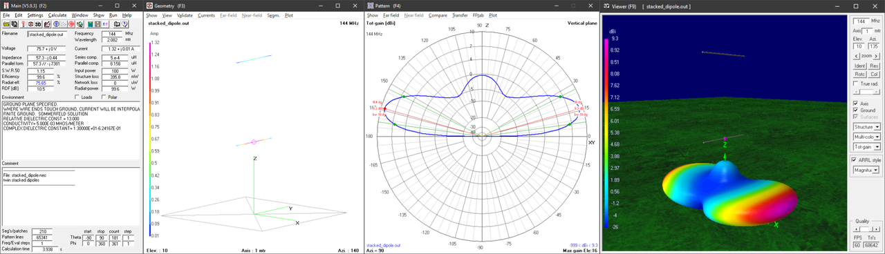
as you can see, the "upper dipole" has the effect of "squishing" the lobe so lowering the takeoff angle and increasing the gain, the typical "hunch" of the dipole is reduced a lot and this, in turn, results in a gain increase; such an antenna has really "handy" size for the 2m band and may be useful for SOTA or for portable use; also notice that the gain is good even going below the main takeoff angle, it shows 6.6dBi at 8° and 3.26dBi at 5°, not bad I think